19
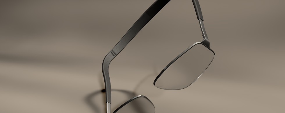
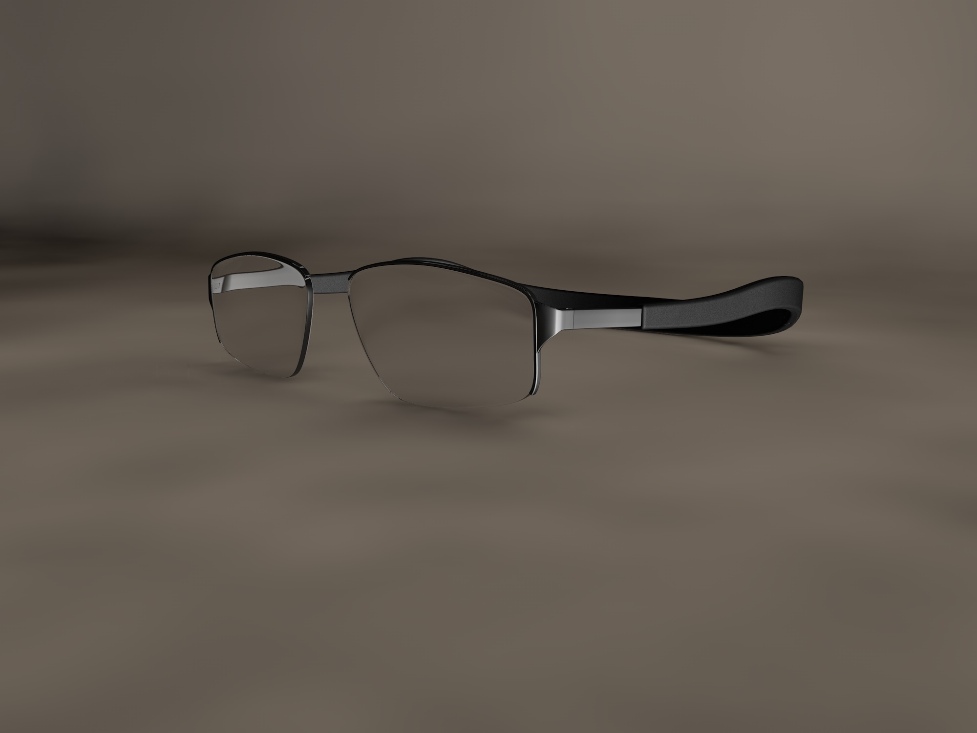
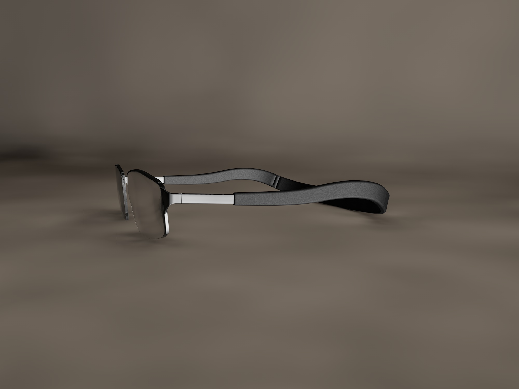
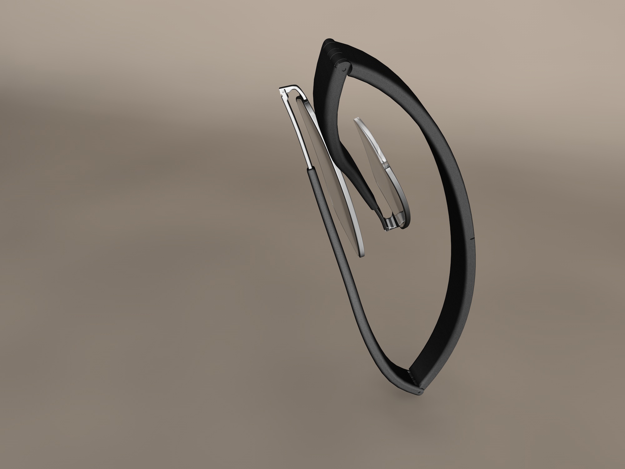
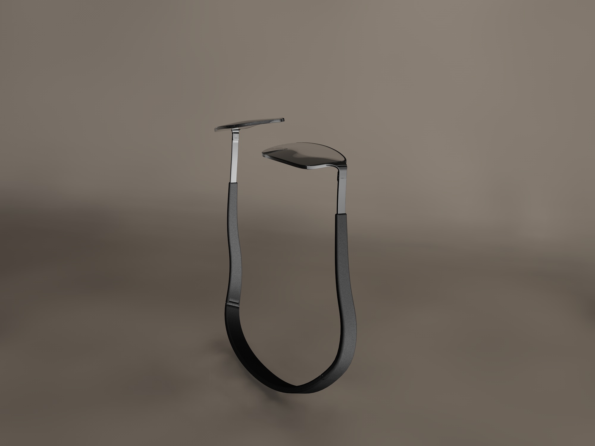
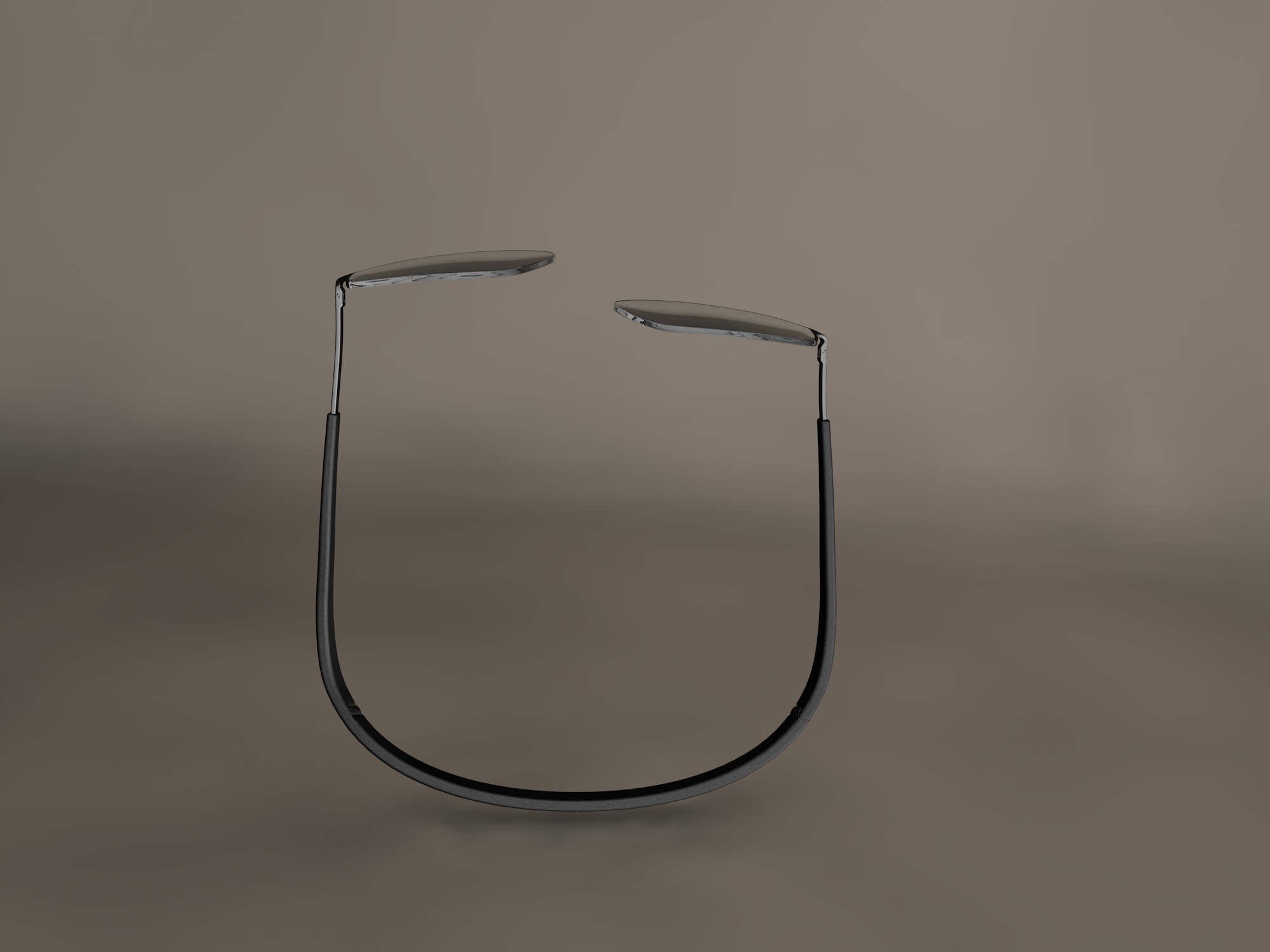
Back | Frame, a generic term for conceiving a different view of the eyeglass frame.
Designed for a personal need, due to the annoying nasal support, I worked out a system to keep the lens in place, eliminating the tedious bridge.
“SƠspesio” is the name coined for this project.
Thanks to the back | frame, “back | frame”, found a number of practical solutions, fulfilling a set of requirements, such as the ability to hold the glasses resting on the neck, without having to use chains, or other accessories, with the advantage have always with you the indispensable accessory. Support system on the head, anchored firmly between his neck and ears, allows it to bend, or make sudden movements, without risking losing his glasses. For a correct focal length, the positioning of the lenses with respect to the eyes, is via the adjustment of the front part of the rods, that are tangent with the lenses, which are composed by a trivial system telescopic.
The closure system requires the division of the glasses in 5 main elements, connected to each other by means of hinges trivial.
This project is protected by official documentation according to the regulations; it can not be copied entirely, neither partially without a written consent of the author.
Back | Frame, un termine generico per concepire una visione diversa della montatura per occhiali.
Concepita per un’esigenza personale, dovuto al fastidioso appoggio nasale, ho ideato un sistema per poter mantenere le lenti in posizione, eliminando il noioso ponticello.
“sƠspesio” è il nome coniato per questo progetto.
Grazie al retro|telaio, “back|frame”, emergono una serie di soluzioni pratiche, che assolvono a un insieme di esigenze, come la possibilità di tenere appoggiato sul collo gli occhiali, senza dover adoperare catenelle, o accessori vari, con il vantaggio di aver sempre con se l’indispensabile accessorio.
Il sistema di appoggio sul capo, ancorato saldamente tra la nuca e le orecchie, permette di potersi chinare, o fare movimenti bruschi, senza rischiare di perdere gli occhiali.
Per una corretta focale, il posizionamento delle lenti rispetto agli occhi, avviene tramite la regolazione della parte anteriore delle bacchette, che sono tangenti con le lenti, i quali sono composti da un banale sistema telescopica.
Il sistema di chiusura, impone la divisione degli occhiali in 5 elementi principali, raccordati tra loro tramite delle banali cerniere.
Questo progetto è protetto da documentazione ufficiale secondo le normative vigenti; non può essere copiato ne interamente, ne parzialmente senza un consenso scritto dell’autore.


07
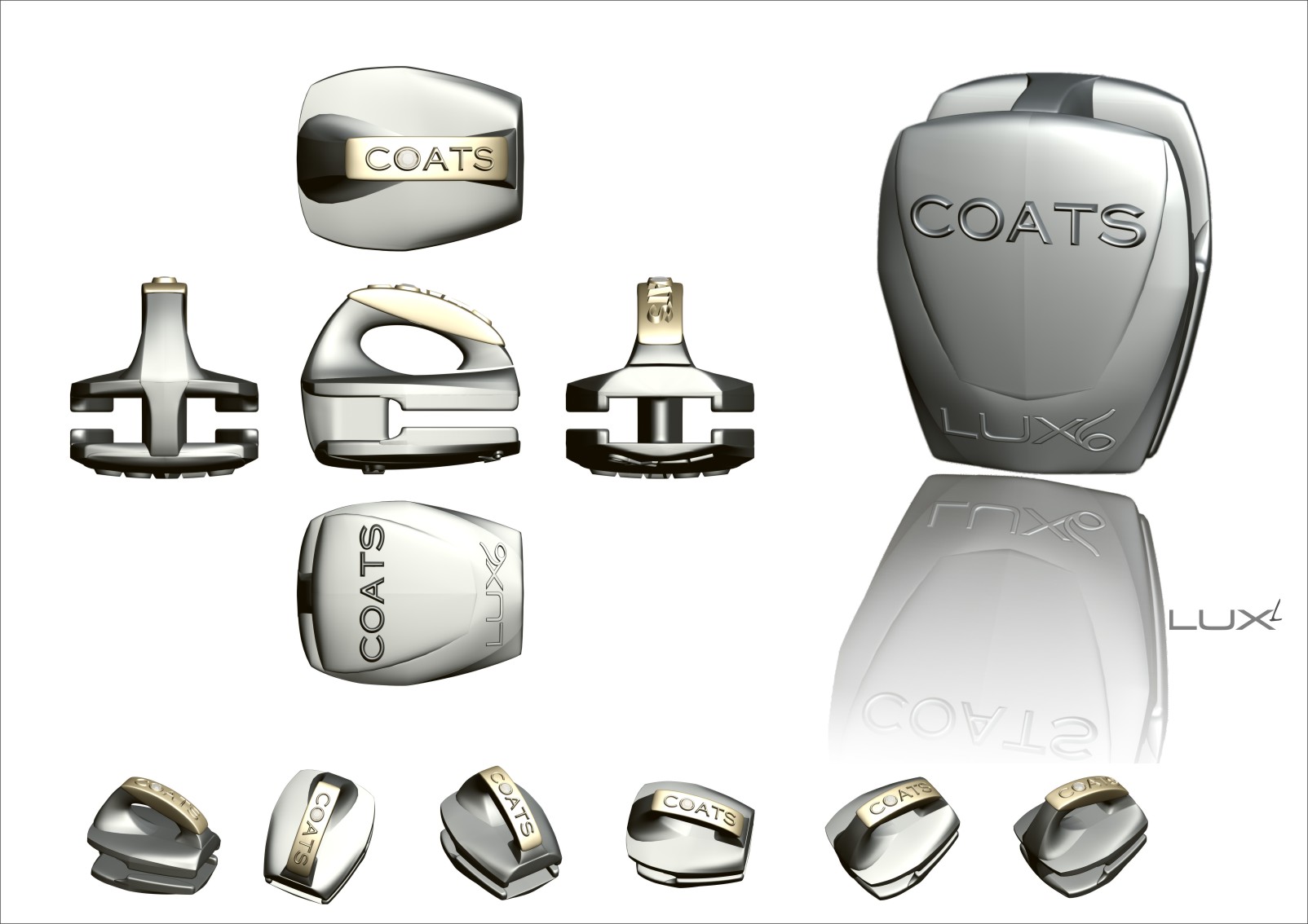
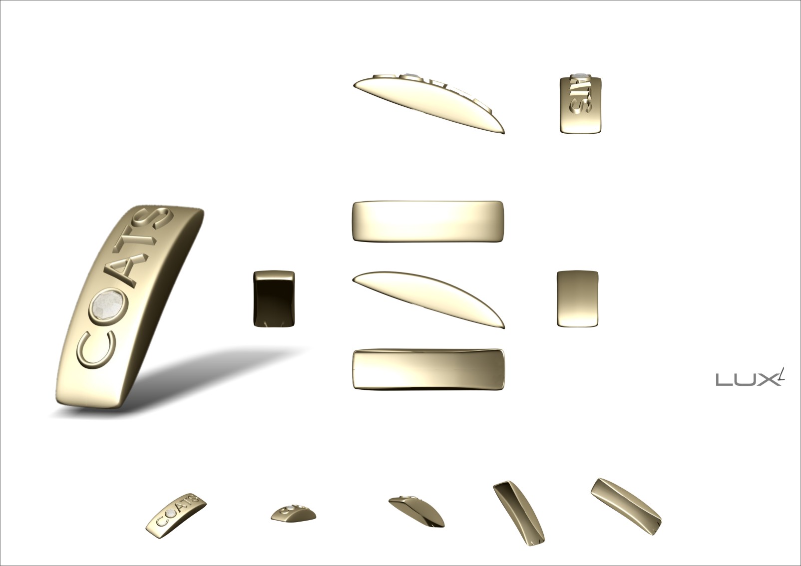
Lux Free is the cursor coordinated with Lux Auto created for Coats. It is a cursor innovative design with the top and bottom customizable. The upper insert is an element that is used to decorate and personalize their accessories, for a nominal charge. It is a project of 2007, which had been one of a kind.
Lux Libero è il cursore in coordinato con Lux Auto creato per la Coats. É un cursore dal design innovativo con la parte superiore ed inferiore personalizzabili. L’inserto superiore è un elemento che serve per decorare e personalizzare i propri accessori, ad un costo irrisorio. É un progetto del 2007, fino ad allora unico nel suo genere.


06
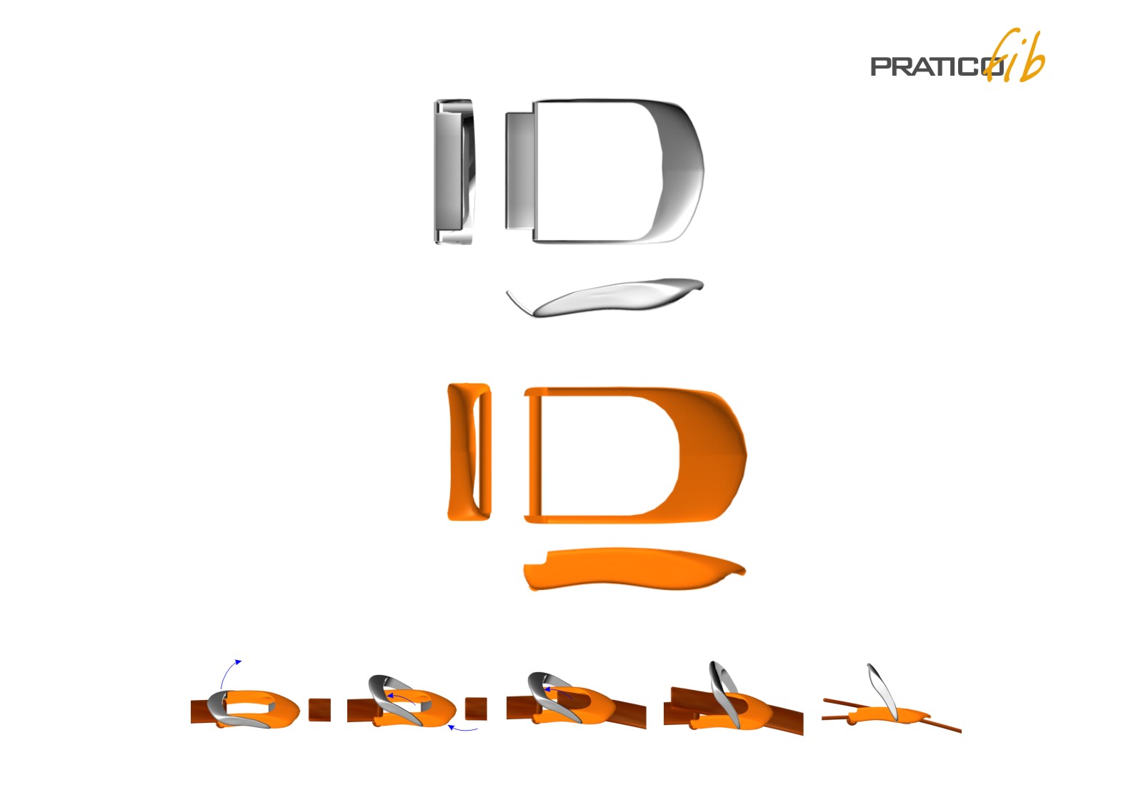
A project carried out in 1998, called “practical” because of its extreme simplicity; He has since opened a new chapter for the accessories going from multicomponent synthesis of single component.
The coordinated “Practical” distances itself from all that has been used before then, for two reasons: the realization of an accessory composed of only two elements, and the development of the coordinated.
The first element: the hook, comprises several functions, and the ability to be able to pinch the placket without the need for a counterpart, has in the property can be anchored to the ammunition of the clothing item with a simple nail rivetable .
All other elements are composed of similar characteristics.
Un progetto realizzato nel 1998, denominato “Pratico”per la sua estrema semplicità; da allora si aprì un nuovo capitolo per l’accessoristica passando dai multicomponenti alla sintesi dei monocomponenti.
Il coordinato “Pratico” si distanzia da tutto ciò che è stato utilizzato prima di allora per due motivi: la realizzazione di un accessorio composto da due soli elementi, e lo sviluppo del coordinato.
Il primo elemento: il gancio, si compone di più funzioni, oltre alla capacità di poter pinzare la paramontura senza aver la necessità di una controparte, ha in se la proprietà di poter essere ancorato alla montura del capo d’abbigliamento con un semplice chiodo rivettabile.
Tutti gli altri elementi si compongono di caratteristiche simili.
-

- Gancio per abbigliamento, o per bretella, composto da 2 parti in zama e nylon, rivettabile al capo di abbigliamento con un chirdo ad espansione.

-

- Gancio per abbigliamento, o per bretella, composto da 2 parti in zama e nylon, rivettabile al capo di abbigliamento con un chirdo ad espansione.

-

- Fibbia in nylon e zama, composta da 2 parti.

-

- Fibbia in nylon e zama, composta da 2 parti.
-

- Fibbia in nylon e zama, composta da 2 parti.

-

- Finecorda oer abbigliamento, composto da 2 parti in zama e nylon.

-

- Finecorda per abbigliamento, composto da 2 parti in zama e nylon.

-

- Bloccacorda in nylon e zama, composto da 2 parti.

-

- Bloccacorda in nylon e zama, composto da 2 parti.

-

- Tiretto, composto da 2 parti.

-

- Tiretto, composto da 2 parti.


05
A major Japanese company, YKK, he commissioned a number of works, made in 2001.
For the first time I managed to overcome myself, creating a unique accessory for the clothing sector.
“Cordlock Stopper” is a cam for clothing, which has the ability to get stuck on the cap tether, even if it is mounted on the head and has the terminal part of the rope sewn on the head.
Characterized in that it is composed of only two parts, it possesses a number of properties:
A button, with which it decreases tension on the cords, to adjust it;
a spring, which keeps the button in tension and ensure a stop to the cord;
a double hole, while having a simple initial crack, the possibility of being made of different plastic materials, such as ABS, and Nylon;
the inability to be released once inserted, (to prevent theft).
All projects had some inventive features, these can be patented.
Una importante azienda giapponese, YKK, mi commissionò una serie di lavori, realizzati nel 2001.
Per la prima volta riuscii a superare me stesso, realizzando un accessorio unico per il settore dell’abbigliamento.
“Cordlock Stopper” è un fermacorda per abbigliamento, che ha la capacità di incastrarsi sul cordoncino del cappuccio, anche se questo è montato sul capo e ha la parte terminale della corda cucita sul capo.
Caratterizzato dal fatto che è composto da due sole parti, possiede una serie di proprietà:
- Un pulsante, con il quale si diminuisce la tensione sul cordoncini, per regolarlo;
- una molla, che mantiene il pulsante in tensione e assicura un freno al cordoncino;
- un doppio foro, pur avendo una semplice fessura iniziale, la possibilità di essere realizzato in diversi materiali plastici, come ABS e Nylon;
- l’impossibilità di essere sganciato una volta inserito, (per evitare il furto).
Tutti i progetti avevano delle caratteristiche inventive, tali da poter essere brevettati.


05
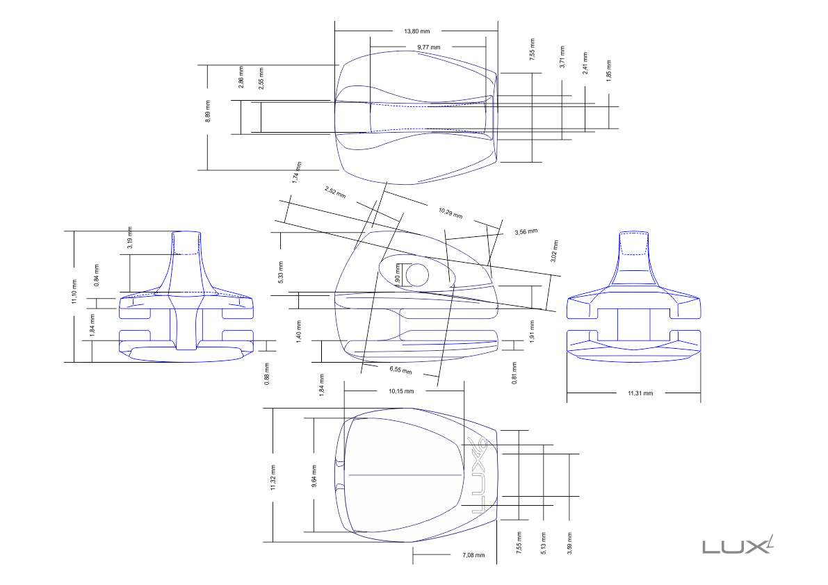
This project for invention has been realized for the Ri.Ri. (2003). It is a cursor for zippers, quick connection and self-locking; the puller can be inserted and unhooked also zipper assembled.
The special feature of this accessory is to be composed of two parts only, a project that led him to be one of a kind.
The first slider, made in the 90s, with the same characteristics was developed by YKK, (a Japanese corporation), with the difference that is made up of as many as 7 elements, including two small springs with an outside diameter of less than one millimeter.
The spring / cap multi-functional, has the property itself to possess three fundamental elements:
a spring, to hold the pull-tab and stop the cursor a cap, which replaces the trigger, with 2 terminal pins that have the function of blocking the cursor the particular design of the same which allow a coupling of the cursor, holding it.
The cap makes the design of the cursor unique.
Questo progetto di invenzione è stato ceduto alla la Ri.Ri. (2003).
Si tratta di un cursore per cerniere, ad innesto rapido ed auto-bloccante; il tiretto puo essere inserito e sganciato anche a cerniera montata.
La particolarità di questo accessorio è di essere composto da 2 sole parti, un progetto che lo porta ad essere unico nel suo genere.
Il primo cursore, realizzato negli anni 90, con le medesime caratteristiche è stato realizzato dalla YKK, (una multinazionale giapponese), con la differenza che è composto da ben 7 elementi, includendo 2 piccole molle con un diametro esterno inferiore al millimetro.
La molla/cappuccio multi-funzionale, ha la proprietà in se di possedere 3 fondamentali elementi:
- una molla, per trattenere il tiretto e fermare il cursore
- un cappuccio, che sostituisce il grilletto, con 2 perni terminali che hanno la funzione di bloccare il cursore
- il disegno particolare degli stessi che permettono un innesto del cursore, trattenendolo.
Il cappuccio rende il design del cursore unico nel suo genere.
16 novembre 2004 n°. EP 1827159 (A2) Brevetto RiRi

-

-
Left: body section zipper.
Right: section of the bridge, elastic spring and small tooth blocker, in a single element.
Sinistra: sezione del corpo zipper. Destra: sezione del ponticello, molla elastica e dentino bloccante, in un unico elemento.

05
A device for sealing chains zipper (zip) of clothing or similar.
Dispositivo per l’ermetizzazione delle catene per cerniere (zip) dei capi d’abbigliamento o simili.
The present invention relates to a sealing system in continuous chain, for all types of hinges (zip) for clothing, bags, shoes or the like. The invention of the invention has the particularity to make the chains of the hinges (zip) to clothing or the like, hermetic, based on an application defined as supra-extrusion, which is a gasket over-extruded subsequent to the production of the chain hinges (zip).
Il presente trovato ha come oggetto un sistema d’ermetizzazione in catena continua, per tutti i tipi di cerniere (zip) per i capi d’abbigliamento, borse, calzature o simili. L’invenzione del trovato ha la particolarità di rendere le catene delle cerniere (zip) per abbigliamento o simili, ermetiche, basandosi su un’applicazione definibile come sovra-estrusione, la quale è una guarnizione sovra-estrusa successiva alla produzione della catena per cerniere (zip).


30
DEVICE FOR THE END OF A CHAPTER OF CLOTHING OR SIMILAR, HIGH EASE OF USE.
DISPOSITIVO PER LA CHIUSURA DI UN CAPO DI ABBIGLIAMENTO O SIMILE, AD ELEVATA FACILITÀ D’USO.
See also C•L•A Zip magnetica | 2º patent
See the video
Dedicated website www.cla.it
The present invention is a device for the closure of an item of clothing or the like, with high ease of use.
The device is formed by a closure member consists of two elements associated respectively to the ammunition and the placket of the garment and can be mutually coupled in order to implement the closure of the garment.
It characterized in that the device according to the invention is composed of two elements that associating a point to any of these said elements are coupled automatically, determining the closing of the article of clothing or the like.
Il presente trovato è un dispositivo per la chiusura di un capo di abbigliamento o simile, ad elevata facilità d’uso.
Il dispositivo è formato da un organo di chiusura composto da due elementi associabili rispettivamente alla montura e alla paramontura del capo di abbigliamento e reciprocamente accoppiabili per attuare la chiusura del capo di abbigliamento.
Caratterizzato dal fatto che il dispositivo secondo il trovato è composto da due elementi che associandone un punto qualsiasi dei detti elementi questi si accoppiano automaticamente, determinando la chiusura del capo di abbigliamento o simile.


There are already known several types of devices for performing the closure of an item of clothing, a pocket, a bag or a camping tent, ranging from the hinges, to devices to hook, by snap hooks, to the more traditional buttons or booties automatic.
Such devices of the known type have the drawback of often be of little practical use, as regards the operation of opening and closing of the garment or the like. In particular in devices of traditional type, to effect opening or closing of the garment, it is necessary the direct intervention of the user on each of the organs used, such as over the entire zipper by sliding a cursor, on each button or hook, and so on.
Aim of the present invention is to solve the above problem expressed, by providing a device for closing the article of clothing or the like, which has high high ease of use, and which makes particularly easy the operation of opening and closing the garment by the user.
Within this aim, an object of the invention is to provide a device which allows the user to effect the closing and the opening of the garment without intervening directly on each of the organs or used by sliding a slider along them , to obtain the closure or opening of the garment or the like.
Another object of the invention is to, provide a device for closing a head clothing or the like which can be manufactured at competitive costs.
This aim, these objects and others which will become apparent hereinafter are achieved by a device for the closure of an item of clothing or the like, comprising a closure member consists of two elements associated respectively to the ammunition and the placket of the garment and mutually coupled in order to implement the closing of the article of clothing or the like, characterized in that said elements contain magnets that allow with their magnetic property to mate and separate according to the needs of ‘user.
The advantages of the invention will become apparent from the description of a preferred embodiment but not exclusive, illustrated by way of non-limitative example in the accompanying drawings, in which:
Figure 1 shows the device according to the invention applied to an article of clothing;
Figure 2 shows the device according to the invention similarly to Figure 1, but in the phase of opening or closing;
Figure 3 shows the device according to the invention, represented with the closure member, partially sectioned;
Figure 4 shows the device according to the invention similarly to Figure 3, but in the phase of opening or closing;
Figure 5 is a section of figure 3, the anoint the horizontal axis, intended for the vertical axis that runs through the device according to the invention along its length, as shown in Figure 3;
Figure 6 shows the device according to the invention similarly to Figure 5, but in the open condition;
Figure 7 illustrates the organ 2A in a perspective view;
Figure 8 illustrates the organ 2B in perspective view;
With reference to the above figures, the device according to the invention, generally indicated by the reference number 1, comprises the closure member 2, which consists of two elements 2A and 2B which are associated respectively to the montura 5 and 6 placket the garment, as shown in Figure 1.
The organ 2, and manually operable to implement the mutual coupling of the two elements that compose 2A and 2B, to obtain the magnetic closure of the garment.
The device according to the invention 2, is composed of two opposing elements separate from one another 2A and 2B, which contain a series of magnets 2C, of cylindrical shape, placed in parallel between them and, consequently, of indefinite number, positioned horizontally with respect to the vertical of the device 2, in the embodiment illustrated in Figure 3.
The magnets 2C, may have different sizes and shapes according to the needs of the closure, the description of a preferred embodiment is the exclusive way of an indicative but not limitative.
The magnets 2C, is placed on the element that the element 2A 2B, maintain one of the two circular bases discovery, until the magnets of the element 2A, can attract fit together respectively, and consequently with the magnets of the element 2B, realizing the closure consequential of the device according to the invention, as illustrated in Figure 4.
The bases discoveries of the magnets 2C, on the element 2A maintain equal sign polar, destined to engage for coupling with the magnets of the element 2B, which maintain between them equal sign polar, but polo opposite to the magnets of the element 2A.
The element 2A, is completed along its entire vertical length by a flattened portion 2F, of reduced thickness which has the function of allowing the sewing or heat sealing of the element 2A directly on montura 5, of the garment. By ATRA ends of the element 2A, along its entire length, there is a corridor 2D, the shape of preferred but not exclusive which has the function of driving, in the coupling step for the element 2B, besides the corridor 2D, has the function of obstructing the passage of water and wind, allowing an airtight seal.
The element 2B, as the element 2A, is traversed along its entire length by a flattened portion 2G, of reduced thickness which has the function of allowing the sewing or heat sealing of the element 2B directly on montura 6, of the head of clothing. The connection body 2 with the garment can still be implemented via other connection means of known type, as for example by gluing.
The magnets 2C, the device according to the invention 2, are spaced apart from each other to give comfortable to mobility organ, also in the coupling step.
The two elements 2A and 2B, the device according to the invention 2, is made in a single piece by molding of synthetic material, incorporating the magnets 2c.
It is ascertained and in practice, how the device according to the invention fully achieves the intended aim, since it allows, in a very quick and simple, to obtain the closing and the opening of an article of apparel or the like, by means of an operation.
The device is susceptible of modifications and variations, all falling within the inventive concept; Moreover, all the details may be replaced by other technically equivalent elements. In practice, the materials employed, as well as the dimensions, may be any according to requirements and the state of the technique.
Il presente trovato ha come oggetto un sistema per la chiusura di un capo di abbigliamento o simile, ad elevata facilità d’uso.
Sono gia noti molteplici tipi di dispositivi per eseguire la chiusura di un capo di abbigliamento, di una tasca, di una borsa o di una tenda da campeggio, che vanno dalle cerniere, ai dispositivi a gancio, dai moschettoni, ai più tradizionali bottoni o bottini automatici.
Tali dispositivi di tipo noto denotano l’inconveniente di risultare spesso di impiego poco pratico, per quanto concerne l’operazione di apertura e di chiusura del capo di abbigliamento o simile. In particolare nei dispositivi di tipo tradizionale, per effettuare l’apertura o la chiusura del capo di abbigliamento, è necessario l’intervento diretto dell’utilizzatore su ciascuno degli organi utilizzati, come ad esempio su tutta la cerniera facendo scorrere un cursore, su ciascun bottone o gancio, eccetera.
Compito del presente trovato è quello di risolvere il problema sopra espresso, realizzando un dispositivo per la chiusura del capo di abbigliamento o simile, che presenti un’elevata ad elevata facilità d’uso e che renda particolarmente agevole l’operazione di apertura e di chiusura del capo di abbigliamento da parte dell’utilizzatore.
Nell’ambito di questo compito, uno scopo del trovato è quello di realizzare un dispositivo che consenta all’utilizzatore di effettuare la chiusura e l’apertura del capo di abbigliamento senza intervenire direttamente su ciascuno degli organi utilizzati o facendo scorrere un cursore lungo di essi, per ottenere la chiusura o l’apertura del capo di abbigliamento o simile.
Un altro scopo del trovato è quello di, realizzare un dispositivo per la chiusura di un capo abbigliamento o simile che possa essere prodotto con costi competitivi.
Questo compito, nonché questi ed altri scopi che meglio appariranno in seguito, sono raggiunti da un dispositivo per la chiusura di un capo di abbigliamento o simile, comprendente un organo di chiusura composto da due elementi associabili rispettivamente alla montura e alla paramontura del capo di abbigliamento e reciprocamente accoppiabili per attuare la chiusura del capo di abbigliamento o simile, caratterizzato dal fatto che detti elementi contengono dei magneti che permettono con la loro proprietà magnetica di accoppiarsi e separarsi a secondo delle esigenze dell’ utilizzatore.
I vantaggi del trovato risulteranno maggiormente dalla descrizione di una forma di esecuzione preferita ma non esclusiva illustrata a titolo indicativo ma non limitativo, negli uniti disegni, in cui:
la figura 1 illustra il dispositivo secondo il trovato applicato ad un capo di abbigliamento;
la figura 2 illustra il dispositivo secondo il trovato analogamente alla figura 1, ma nella fase di apertura o chiusura;
la figura 3 illustra il dispositivo secondo il trovato, con rappresentato l’organo di chiusura, parzialmente sezionato;
la figura 4 illustra il dispositivo secondo il trovato analogamente alla figura 3, ma nella fase di apertura o chiusura;
la figura 5 è una sezione della figura 3, eseguita l’ungo l’asse orizzontale, intesa per verticale l’asse che percorre il dispositivo secondo il trovato lungo la sua estensione, come illustrato nella figura 3;
la figura 6 illustra il dispositivo secondo il trovato analogamente alla figura 5, ma nella condizione di apertura;
la figura 7 illustra l’organo 2A in vista prospettica;
la figura 8 illustra l’organo 2B in vista prospettica;
Con riferimento alle figure citate, il dispositivo secondo il trovato, indicato globalmente con il numero di riferimento 1, comprende l’organo di chiusura 2, il quale e composto da due elementi 2A e 2B che sono associabili rispettivamente alla montura 5 e alla paramontura 6 del capo di abbigliamento, come illustrato nella figura 1.
L’organo 2, e azionabile manualmente per attuare il reciproco accoppiamento dei due elementi che lo compongono 2A e 2B, per ottenere la chiusura magnetica del capo di abbigliamento.
Il dispositivo secondo il trovato 2, è composto da due elementi contrapposti distinti tra loro 2A e 2B, che contengono una serie di magneti 2C, di forma cilindrica, posti parallelamente e conseguentemente tra loro, di numero indefinito, posizionati orizzontalmente rispetto alla verticale del dispositivo 2, nella forma di esecuzione illustrata nella figura 3.
I magneti 2C, possono avere dimensioni e forme differenti a secondo delle esigenze della chiusura, la descrizione di una forma di esecuzione preferita è esclusiva a titolo indicativo ma non limitativo.
I magneti 2C, posti sia sull’elemento 2A che sull’elemento 2B, mantengono una delle due basi circolari scoperta, a finché i magneti dell’elemento 2A, possono attrarsi combaciare rispettivamente e conseguentemente con i magneti dell’elemento 2B, realizzando la chiusura consequenziale del dispositivo secondo il trovato, come illustrato nella figura 4.
Le basi scoperte dei magneti 2C, sull’elemento 2A mantengono uguale segno polare, destinati ad impegnarsi per l’accoppiamento con i magneti dell’elemento 2B, che mantengono tra loro uguale segno polare, ma di polo contrario ai magneti dell’elemento 2A.
L’elemento 2A, è completato lungo tutta la sua lunghezza verticale da una porzione appiattita 2F, di ridotto spessore che ha la funzione di consentire la cucitura o la termosaldatura del l’elemento 2A direttamente sulla montura 5, del capo di abbigliamento. Dall’atra estremità dell’elemento 2A, lungo tutta la sua lunghezza, vi è un corridoio 2D, di forma preferita ma non esclusiva che ha la funzione di guida, nella fase di accoppiamento per l’elemento 2B, inoltre il corridoio 2D, ha la funzione di ostruire il passaggio dell’acqua e del vento, permettendo una chiusura ermetica.
L’elemento 2B, come l’elemento 2A, è percorso lungo tutta la sua lunghezza da una porzione appiattita 2G, di ridotto spessore che ha la funzione di consentire la cucitura o termosaldatura del l’elemento 2B direttamente sulla montura 6, del capo di abbigliamento. La connessione dell’organo 2 al capo di abbigliamento può comunque essere attuata mediante altri mezzi di connessione di tipo noto, come ad esempio mediante incollaggio.
I magneti 2C, del dispositivo secondo il trovato 2, sono distanziati tra loro per dare agio alla mobilità all’organo, anche nella fase di accoppiamento.
I due elementi 2A e 2B, del dispositivo secondo il trovato 2, è realizzato in un unico pezzo mediante stampaggio di materiale sintetico, che incorporano i magneti 2c.
Si e in pratica accertato, come il dispositivo secondo il trovato assolva integralmente il compito prefissato, in quanto consente, in modo estremamente rapido ed semplice, di ottenere la chiusura e l’apertura di un capo di abbigliamento o simile, mediante una operazione.
Il dispositivo è suscettibile di modifiche e varianti, tutte rientranti nell’ambito del concetto inventivo; inoltre, tutti i dettagli potranno essere rimpiazzati da altri elementi tecnicamente equiparabili. In pratica, i materiali impiegati, nonché le dimensioni, potranno essere qualsiasi secondo le esigenze e lo stato della tecnica.
1. Device for the closure of an item of clothing or the like, comprising a closure member consists of two elements associated respectively to the ammunition and the placket of the garment and can be mutually coupled in order to implement the closure of the garment, characterized in that the device according to the invention is composed of two elements which, by associating any point of the said elements, these are coupled automatically, determining the closing of the article of clothing or the like.
2. Device, according to claim 1, characterized in that in the two elements of the said member there are included a series of magnets which enable the coupling between them, determining the opening or closing of the garment.
3. Device, according to claims 1 and 2, characterized in that said elements can mate and separate at any point along the closure end of the organ, causing the closing or the opening of the item of clothing or similar.
4. Device according to one or more of the preceding claims, characterized in that an element of the organ according to the invention, has all along one of its ends a corridor, has the function of driving, in the coupling step of said element of ‘ organ, besides the corridor has the function of obstructing the passage of water and wind, allowing an airtight seal.
5. Device according to one or more of the preceding claims, characterized in that, the magnets of the device according to the invention, are spaced from each other to give comfortable to mobility organ, also in the coupling step.
6. Device for the closure of an item of clothing or the like, characterized in that it comprises one or more of the described and / or illustrated.
1. Dispositivo per la chiusura di un capo di abbigliamento o simile, comprendente un organo di chiusura composto da due elementi associabili rispettivamente alla montura e alla paramontura del capo di abbigliamento e reciprocamente accoppiabili per attuare la chiusura del capo di abbigliamento, caratterizzato dal fatto che il dispositivo secondo il trovato è composto da due elementi che, associando un punto qualsiasi dei detti elementi, questi si accoppiano automaticamente, determinando la chiusura del capo di abbigliamento o simile.
2. Dispositivo, secondo la rivendicazione 1, caratterizzato dal fatto che nei due elementi del detto organo vi sono compresi una serie di magneti che permettono l’accoppiamento tra loro, determinando la chiusura o l’apertura del capo di abbigliamento.
3. Dispositivo, secondo le rivendicazioni 1 e 2, caratterizzato dal fatto che detti elementi possono accoppiarsi e separarsi in qualsiasi punto lungo l’estremità di chiusura dell’organo, determinando la chiusura o l’apertura del capo di abbigliamento o simile.
4. Dispositivo, secondo una o più delle rivendicazioni precedenti, caratterizzato dal fatto che un elemento dell’organo secondo il trovato, ha lungo tutta una sua estremità un corridoio che, ha la funzione di guida, nella fase di accoppiamento dei detti elemento dell’organo, inoltre il corridoio ha la funzione di ostruire il passaggio dell’acqua e del vento, permettendo una chiusura ermetica.
5. Dispositivo, secondo una o più delle rivendicazioni precedenti, caratterizzato dal fatto che, i magneti del dispositivo secondo il trovato, sono distanziati tra loro per dare agio alla mobilità all’organo, anche nella fase di accoppiamento.
6. Dispositivo per la chiusura di un capo di abbigliamento o simile, caratterizzato dal fatto di comprendere una o più delle caratteristiche descritte e/o illustrate.

30
An improved structures to implement closures for clothing replacement of zippers or pockets.
Dispositivo perfezionato per realizzare strutture per chiusure per capi di abbigliamento sostitutive delle cerniere lampo o zip.
See also C•L•A Zip magnetic | 1st patent
See the video
Dedicated website www.cla.it

The invention concerns a device for the closure of an item of clothing, but not only, and in particular it refers to an alternative replacement in devices, known as zippers (zip), Velcro or the like, used for the union of two flaps of fabric defining an opening / closing elongated, such as the area defined “flap” of the pants, pockets or the like, or for the opening and closing of bosses in gender.
The present invention relates in particular to improvements made to a device, used for the union of two flaps of fabric, or other, defining an elongate opening which exploits the magnetic attraction object of the previous patent application No. MI2001A 2316 filed on 6:11 .2001 by the applicant.
The improvements of this new patent application are such as to increase the functionality of the device, the subject of the previous question, widening its scope even in the rare cases where the use of the previous device could be contraindicated, while achieving a flexible and soft structure, obviating the excessive pliability of the fabric normally used as a support of this type of magnetic closure.
Advantageously, the device for the union, the present invention also solves the problems related to other devices based on magnetism, such as those in which the union of two flaps of fabric or the like is obtained by overlapping the edges of the fabric, with consequent formation of an undesired extra thickness at the joints, as in the case of the system shown for example by US patent 2249267, 09.04.79 10.02.81 in the name Clifford C. Voss or in US Patent 6,434,801 20.08.2002 6.4.2001 on behalf of Sama.
The indicated aims and others which will become apparent hereinafter, are achieved by the device for the closure of an item of clothing but not only, therefore also for leather goods or other, comprising a closure member consists of two elements associated respectively to the ammunition and to the placket of the garment and mutually joinable to one another via magnetic coupling in the lateral plane and is characterized by the fact of being realized using two segments, obtained by cutting suitably a continuous structure, consisting of two strips of flexible material, such as material plastic, fabric, natural or synthetic leather, expecting at least one lateral protrusion for the union to the article of clothing or the like, to which must be applied, between which is inserted and suitably fixed a layer of spongy material, provided with suitably spaced locations between them adapted to receive and hold a series of magnetic elements prevedenti means to concentrate in the desired direction, the magnetic flux generated while reducing the spread in other directions of the flux generated by the magnet, used in order to minimize any side effects of the magnetic field, in against persons or objects magnetically influenced.
It ‘well known that during the use of magnetic closures for items of clothing, such as “poppers” magnetic packs used for sports, such as wind jackets, vests and the like, problems may occur in the case where said elements did not run casually in close proximity to magnetically sensitive equipment, such as the so-called “peace-maker” external or subcutaneous. Therefore – even if in the case of magnetic closures, whereas the lower power of the magnets used and the different arrangement of the same, the risk of interference with equipment magneto-sensitive course of the garment worn by the user, is surely minor – the main purpose of the present invention is to make available to the operators of the clothing industry, a magnetic closing system with improved security guarantees greater than those of similar products currently in use. Moreover, the same elements provided to concentrate the magnetic flux in the desired direction, increase the attraction force contact.
Another object is to provide a magnetic closure for items of clothing or other, in which it is possible to easily maintain a partial opening of the same, thanks to the presence of elements to retain only a part of the magnets, away from the magnets of opposing engagement, obtaining one or more openings at the moment blocked.
Moreover, the device according to the invention, providing for the improvements indicated, is achievable at reduced cost and thus can be also applied to different supports, cloth, plastic, etc. for closing applications not only in the field of clothing and leather articles or the like, but also for therapeutic applications and / or functional in all those applications where it is necessary to have a system of union quickly and free of thickenings at the point of union: laces, bandages, etc.
The advantages of the invention become apparent from the description of some preferred but not exclusive embodiment, illustrated only by way of non limiting indication in the accompanying drawings, in which:
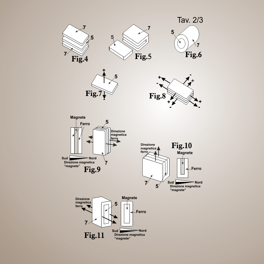
Fig. 1 illustrates a front view of a magnetic closure made using two segments of the structure of the improved device according to the invention;
Fig. 2 shows, schematically and in section along the line xx of the device according to the invention;
Fig. 3 is a perspective view to an enlarged stylized separate components (exploded view) of one of the magnetic elements forming part of the closing device referred to in Fig. 1 and 2, highlighting, in a first embodiment, the means for it focus and schermarne the magnetic flux;
Fig. 4 is a perspective view to an enlarged stylized separate components (exploded view) of one of the magnetic elements forming part of the closure device of Fig. 1 highlighting a second embodiment of the means for concentrating and shield the magnetic flux;
The Fig. 5 is a perspective view of one of the enlarged stylized magnetic elements forming part of the closure device of Fig. 1 highlighting a third embodiment of means for concentrating and shield the magnetic flux in the presence of magnetic elements is substantially cylindrical;
The Fig. 6 schematically illustrates the direction of the magnetic flux, coming from one of the magnetic elements of Figures 3, 4, 5, devoid of means of concentration and shielding;
The Fig. 7 schematically illustrates the direction of the magnetic flux coming from one of the magnetic elements of Figures 3, 4, 5, 6, provided with means of concentration and shielding;
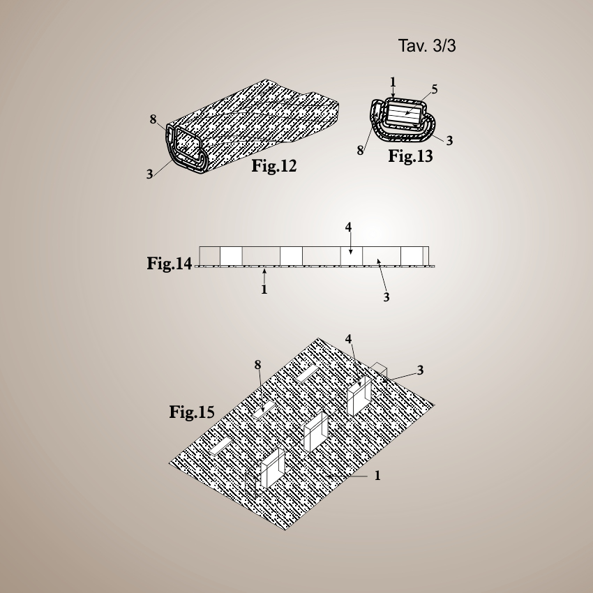
Referring to the figures, the closing device according to the present invention is carried out using two segments, indicated by way of example with A and B, obtained by cutting suitably a continuous structure 1 which is characterized by the fact of being formed by a lower layer or the base 2, made of a material of suitable consistency and thickness, which fabric, leather, or other material with characteristics of flexibility and strength suitable, to which is superimposed and joined by gluing or other suitable joining technique, a continuous layer 3 of spongy material provided with seats 4 suitably spaced apart for receiving and retaining a series of magnetic elements 5, said structure 1 being completed by a top layer or cover 6 made of a material having structural preferably but not exclusively similar to those of the layer of the bottom 2, 3 joined to the underlying layer of spongy material by gluing or other joining technique suitable after insertion and fixing in the alveoli of the magnetic elements 5 are arranged in succession and separated by a predetermined distance with the magnetic poles alternating. The two segments A and B are associated respectively to the ammunition and the placket of a piece of clothing, or the edges of any elongated opening provided in one end of leather or another. Said segments A and B, suitably cut to a length corresponding to the size of the opening to be closed, for the use (union with the garment) will be arranged in opposite directions along the vertical axis of said opening, so affect totally or partially the length of the opening to be closed and joined, by sewing or other suitable technique of union to the fabric or other material with which the product is made (item of clothing, bag, etc.) with which the closure according to the invention must be applied and they provide incorporated a series of alternating metal plates 8 arranged in correspondence with the edge opposite to that in which they are combined the magnetic elements 5. Said segments A and B are obtained by cutting, for example but not exclusively, with a scissors, the structure 1 produced in rolls, carrying out the cut in correspondence of the intermediate spaces between the magnets 5 are arranged in succession. The positioning of the closure according to the invention on the article of clothing or another will be carried out on the flat laterally juxtaposing the segments A and B so that the magnets can attract each 5 incorporated in them thanks to the alternating opposite polarity without superimposing the structure 1 as a whole and then without affecting substantially on the thickness of the head in correspondence of the area where said structure is applied
The magnetic elements 5 are constituted for example by micro-Neodymium magnets or other magnetic alloy suitable artificial, plastoferrite or other, and are inserted and held in the structure 1 so as to maintain a stripped end so that the opposite poles attract each can, realizing l ‘ consequential union of all the magnets in fact closing the opening at the sides of which there are arranged.
The magnetic elements 5 can be joined to the spongy layer 3 in any suitable manner, for example gluing or stitching them in the thickness of the material, or even termofissandoli to the material in the presence of heat-formable material, or even embedding in the material of the structure 1 during its formation, for example by a process of co-extrusion or thermo-continuous union of the components defining the three layers of the structure 1 itself with simultaneous insertion of the magnets 5 in the alveoli of the spongy layer 3. Moreover, even if not indispensable, before the fixing of the segments A and B to the piece of clothing or other may be provided, at one end of one of the two segments A and B, an element facilitator of the separation of the magnets constituted for example by a tongue suitably shaped and challenged with two fingers (not illustrated) fixed in a suitable way.
Again with reference to the figures, the magnetic elements opposing generically indicated with reference numeral 5, are fitted with means 7, acts to concentrate in the desired direction, the magnetic flux generated while reducing the spread in the other directions. Said means concentrators / schermatori 7 are of a size and shape complementary to that of the magnets 5 and are constituted by a metal structure adherent, suitably shaped and joined to each magnet via suitable fixing means. In the case of substantially flat magnets (parallelepipeds of reduced thickness), the metal structure will consist of two plates joined to the major sides of the magnet itself, or from a metal plate bent into a U-embracing three sides of the magnet. In the case of substantially cylindrical magnets, the metal structure constituting the means concentrators / schermatori will be substantially constituted by a metal sheath appropriately sized and shaped adapted to wrap laterally said magnetic elements. The sheathing of the magnetic elements may however also be used for all types of magnets substantially flat or of any shape and be obtained by continuing operations of winding or extrusion or co-extrusion, followed by slicing (portioning) into portions of the magnetic material coated .
The materials and the dimensions both of the magnetic elements 5 is of the structure 1 support may be any according to requirements, as may be the fastening means of the various components between them. In fact, the section of the magnets may be any, for example to adjust, then rectangular, triangular, hexagonal, circular, oval, etc. or any irregular, as well as the spongy layer 3 can be made with different materials and with seats for housing the magnets 5 of any shape and size compatible with those of the magnets themselves to be inserted, without prejudice to the distances of interposition between the magnets themselves , distances that are calculated based on the characteristics of the magnets to be embedded. All without departing from the scope of the present patent, as described, illustrated in the accompanying drawings and later claimed.
L’invenzione concerne un dispositivo per la chiusura di un capo d’abbigliamento, ma non solo ed in particolare si riferisce ad un’alternativa sostitutiva nei dispositivi, noti come cerniere lampo (zip), velcro od altro, utilizzati per l’unione di due lembi di stoffa definenti un’apertura/chiusura allungata, quali ad esempio la zona definita “patta” dei pantaloni, delle tasche o simili, oppure per l’apertura e chiusura di capi in genere.
La presente invenzione riguarda in particolare dei perfezionamenti apportati ad un dispositivo, utilizzate per l’unione di due lembi di stoffa o altro, definenti un’apertura allungata che sfrutta l’attrazione magnetica oggetto della precedente domanda di brevetto No. MI2001A 2316 depositata il 6.11.2001 dal richiedente.
I perfezionamenti oggetto di questa nuova domanda di brevetto sono tali da incrementare la funzionalità del dispositivo, oggetto della domanda precedente, ampliandone il campo di applicazione anche nei rari casi in casi in cui l’uso del dispositivo precedente poteva essere controindicato, realizzando nel contempo una struttura flessibile e morbida, ovviando alla eccessiva pieghevolezza del tessuto abitualmente utilizzato come supporto di questo tipo di chiusura magnetica.
Vantaggiosamente il dispositivo per l’unione, oggetto della presente invenzione risolve anche i problemi legati ad altri dispositivi basati sul magnetismo, ad esempio quelli in cui l’unione di due lembi di tessuto o simile viene ottenuta sovrapponendo i bordi del tessuto, con conseguente formazione di un extra spessore indesiderato nei punti di unione, come nel caso del sistema evidenziato ad esempio dal brevetto americano 2 249 267, 4.9.79 10.02.81 a nome Clifford C. Voss o nel brevetto US 6 434 801 6.4.2001 20.08.2002 a nome Sama.
Gli scopi indicati ed altri ancora che appariranno in seguito, vengono raggiunti dal dispositivo per la chiusura di un capo di abbigliamento ma non solo, quindi anche per prodotti di pelletteria o altri, comprendente un organo di chiusura composto da due elementi associabili rispettivamente alla montura ed alla paramontura del capo di abbigliamento e reciprocamente unibili tra loro, tramite accoppiamento magnetico laterale in piano e si caratterizza per il fatto di essere realizzato utilizzando due segmenti, ricavati tagliando opportunamente una struttura continua, costituita da due strisce di materiale flessibile, quali ad esempio materiale plastico, stoffa, pelle naturale o sintetica, prevedente almeno una propaggine laterale per l’unione al capo di abbigliamento o simile, alla quale deve essere applicata, tra le quali è inserito ed opportunamente fissato uno strato di materiale spugnoso, munito di sedi opportunamente distanziate tra loro atte ad accogliere e trattenere una serie di elementi magnetici prevedenti mezzi per concentrare nella direzione voluta il flusso magnetico generato, riducendo contemporaneamente la diffusione in altre direzioni del flusso generato dal magnete, utilizzato al fine di minimizzare eventuali effetti collaterali del campo magnetico, nei confronti di soggetti od oggetti magneticamente influenzabili.
E’ noto che durante l’utilizzo di chiusure magnetiche per capi di abbigliamento, ad esempio “bottoni automatici” magnetici utilizzati per confezioni sportive, quali giacche a vento, giubbotti e simili, si possono verificare problemi nel caso in cui detti elementi venissero a trovarsi casualmente in stretta vicinanza con apparecchiature sensibili al magnetismo, quali ad esempio i cosiddetti “pace-maker” esterni o sottocutanei. Di conseguenza – anche se nel caso delle chiusure magnetiche, considerando la minore potenza dei magneti impiegati e la differente disposizione degli stessi, il rischio di interferenza con apparecchiature magneto-sensibili portate dall’utilizzatore del capo indossato, è sicuramente minore – lo scopo principale della presente invenzione è quello di mettere a disposizione degli operatori del settore abbigliamento, un sistema di chiusura magnetica perfezionato con garanzie di sicurezza maggiori di quelle dei prodotti similari attualmente in uso. Inoltre gli stessi elementi previsti per concentrare il flusso magnetico nella direzione voluta, ne aumentano la forza di attrazione a contatto.
Un altro scopo è quello di realizzare una chiusura magnetica per capi di abbigliamento o altro, nella quale sia possibile mantenere agevolmente un’apertura parziale della stessa, grazie alla presenza di elementi per trattenere una sola parte dei magneti, lontana dai magneti di impegno opposti, ottenendo una o più aperture momentaneamente bloccate.
Inoltre il dispositivo secondo l’invenzione, prevedente i perfezionamenti indicati, è realizzabile a costi ridotti e quindi può essere anche applicato a supporti diversi, stoffa, plastica, ecc. per applicazioni di chiusura non solo nel campo dell’abbigliamento e della pelletteria o simili, ma anche per applicazioni terapeutiche e/o funzionali in tutte quelle applicazioni in cui sia necessario disporre di un sistema di unione rapido e privo di ispessimenti nel punto di unione: lacci, fasciature, ecc.
I vantaggi dell’invenzione risulteranno maggiormente dalla descrizione di alcune forme preferite ma non esclusive di realizzazione, illustrate a titolo indicativo ma non limitativo negli uniti disegni, in cui:
La Fig. 1 illustra in una vista frontale una chiusura magnetica realizzata utilizzando due segmenti della struttura del dispositivo perfezionato secondo l’invenzione;
La Fig. 2 illustra in modo schematico ed in sezione secondo la linea x-x il dispositivo secondo l’invenzione;
La Fig. 3 è una vista prospettica stilizzata ingrandita a componenti separati (esploso) di uno degli elementi magnetici facente parte del dispositivo di chiusura di cui alle fig. 1 e 2 evidenziante, in una prima forma di esecuzione, i mezzi per concentrarne e schermarne il flusso magnetico;
La Fig. 4 è una vista prospettica stilizzata ingrandita a componenti separati (esploso) di uno degli elementi magnetici facente parte del dispositivo di chiusura di fig. 1 evidenziante una seconda forma di esecuzione dei mezzi per concentrare e schermare il flusso magnetico;
La Fig. 5 è una vista prospettica stilizzata ingrandita di uno degli elementi magnetici facente parte del dispositivo di chiusura di fig. 1 evidenziante una terza forma di mezzi per concentrare e schermare il flusso magnetico in presenza di elementi magnetici sostanzialmente cilindrici;
La Fig. 6 illustra in modo schematico la direzione del flusso magnetico, proveniente da uno degli elementi magnetici di cui alle figure 3, 4, 5, sprovvisto di mezzi di concentrazione e schermatura;
La Fig. 7 illustra in modo schematico la direzione del flusso magnetico proveniente da uno degli elementi magnetici di cui alle figure 3, 4, 5, 6, munito di mezzi di concentrazione e schermatura;
Facendo riferimento alle figure, il dispositivo di chiusura secondo la presente invenzione viene realizzato utilizzando due segmenti, indicati a titolo di esempio con A e B, ricavati tagliando opportunamente una struttura continua 1 che si caratterizza per il fatto di essere costituita da un strato inferiore o fondo 2, realizzato in un materiale di adatta consistenza e spessore, quale stoffa, pelle, o altro materiale dotato di caratteristiche di flessibilità e resistenza adatte, al quale è sovrapposto ed unito per incollaggio o altra tecnica di unione adatta, uno strato continuo 3 di materiale spugnoso munito di sedi 4 opportunamente distanziate tra loro atte ad accogliere e trattenere una serie di elementi magnetici 5, detta struttura 1 essendo completata da uno strato superiore o copertura 6 realizzata con un materiale avente caratteristiche strutturali preferibilmente ma non esclusivamente simili a quelle dello strato di fondo 2, unito al sottostante strato 3 di materiale spugnoso per incollaggio o altra tecnica di unione adatta dopo l’inserimento ed il fissaggio negli alveoli degli elementi magnetici 5 disposti in successione e separati tra loro da una distanza prestabilita con i poli magnetici alternati. I due segmenti A e B sono associabili rispettivamente alla montura ed alla paramontura di un capo di abbigliamento, oppure ai bordi di una qualsiasi apertura allungata prevista in un capo di pelletteria o altro. Detti segmenti A e B, opportunamente tagliati di lunghezza corrispondente alle dimensioni dell’apertura da chiudere, per l’utilizzo (unione al capo di abbigliamento) verranno disposti in modo contrapposto lungo l’asse verticale della detta apertura, in modo interessare totalmente o parzialmente la lunghezza dell’apertura da chiudere ed uniti, per cucitura o altra tecnica adatta di unione, alla stoffa o altro materiale con il quale è costituito il prodotto (capo di abbigliamento, borsa, ecc.) al quale la chiusura secondo l’invenzione deve essere applicata e prevedono incorporate una serie di placche metalliche alternate 8 disposte in corrispondenza del bordo opposto a quello in cui sono abbinati gli elementi magnetici 5. Detti segmenti A e B vengono ottenuti tagliando, ad esempio ma non esclusivamente, con una forbice, la struttura 1 prodotta in rotoli, effettuando il taglio in corrispondenza degli spazi intermedi tra i magneti 5 disposti in successione. Il posizionamento della chiusura secondo l’invenzione sul capo di abbigliamento o altro verrà effettuato giustapponendo in piano lateralmente i segmenti A e B in modo che i magneti 5 in essi incorporati possano attrarsi grazie alle polarità alterne opposte senza sovrapporre la struttura 1 nel suo insieme e quindi senza influire sostanzialmente sullo spessore del capo in corrispondenza della zona in cui detta struttura viene applicata
Gli elementi magnetici 5 sono costituti ad esempio da micro-magneti in Neodimio od altra lega magnetica artificiale adatta, in plastoferrite o altro e sono inseriti e trattenuti nella struttura 1 in modo da mantenere una estremità scoperta affinché i poli opposti possano attrarsi, realizzando l’unione consequenziale di tutti i magneti chiudendo di fatto l’apertura ai lati della quale sono disposti.
Gli elementi magnetici 5 possono essere uniti allo strato spugnoso 3 in un qualsiasi modo adatto, ad esempio incollandoli, oppure cucendoli nello spessore del materiale, od ancora termofissandoli al materiale in presenza di materiale termoformabile, oppure ancora inglobandoli nel materiale della struttura 1 durante la sua formazione, ad esempio tramite un procedimento di co-estrusione o termo-unione continua dei componenti definenti i tre strati della struttura 1 stessa con contemporaneo inserimento dei magneti 5 negli alveoli dello strato spugnoso 3. Inoltre, anche se non è indispensabile, prima del fissaggio dei segmenti A e B al capo di abbigliamento o altro potrà essere previsto, ad una delle estremità di uno dei due segmenti A e B, un elemento facilitatore della separazione dei magneti costituito ad esempio da una linguetta opportunamente sagomata ed impugnabile con due dita (non illustrata) fissata in modo adatto.
Sempre facendo riferimento alle figure, gli elementi magnetici contrapposti indicati genericamente con il riferimento numerico 5, sono muniti di mezzi 7, atti a concentrare nella direzione voluta il flusso magnetico generato riducendone contemporaneamente la diffusione nelle altre direzioni. Detti mezzi concentratori/schermatori 7 sono di dimensioni e sagoma complementare a quella dei magneti 5 e sono costituiti da una struttura metallica aderente, opportunamente sagomata ed unita a ciascun magnete tramite adatti mezzi di fissaggio. Nel caso di magneti sostanzialmente piatti (parallelepipedi di ridotto spessore) la struttura metallica sarà costituita da due piastrine unite ai lati maggiori del magnete stesso, oppure da una lastrina metallica piegata ad U avvolgente per tre lati il magnete. Nel caso di magneti sostanzialmente cilindrici, la struttura metallica costituente i mezzi concentratori/schermatori sarà costituita sostanzialmente da una guaina metallica opportunamente dimensionata e sagomata atta ad avvolgere lateralmente detti elementi magnetici. L’inguainatura degli elementi magnetici potrà comunque essere utilizzata anche per tutti i tipi di magneti sostanzialmente piatti o di sagoma qualsiasi ed essere ottenuta tramite operazioni continue di avvolgimento o trafilatura o co-estrusione, seguite dalla tranciatura (porzionatura) in spezzoni del materiale magnetico rivestito.
I materiali e le dimensioni sia degli elementi magnetici 5 sia della struttura 1 supporto potranno essere qualsiasi a seconda delle esigenze, così come potranno esserlo i mezzi di fissaggio dei vari componenti tra di loro. In effetti la sezione dei magneti potrà essere qualsiasi, ad esempio regolare, quindi rettangolare, triangolare, esagonale, circolare, ovale, ecc. o irregolare qualsiasi, così come lo strato spugnoso 3 potrà essere realizzato con differenti materiali e con sedi per l’accoglimento dei magneti 5 di qualsivoglia forma e dimensione compatibili con quelle dei magneti stessi da inserire, salvi restando le distanze di interposizione tra i magneti stessi, distanze che vengono calcolate in base alle caratteristiche dei magneti da inglobare. Il tutto senza uscire dall’ambito protettivo del presente brevetto, come descritto, illustrato negli uniti disegni e più avanti rivendicato.
1. Improved device for achieving the union of two flaps of fabric, or other, defining elongated closure for items of clothing or the like and in particular closures that exploit the magnetic attraction, characterized in that it is made using two segments obtained by cutting suitably a continuous structure, providing for at least one lateral protrusion for the union to the article of clothing or the like to which must be applied to a structure consisting of: a bottom layer or bottom made of a material of suitable consistency and thickness, such as fabric, leather, or other material with characteristics of flexibility and strength suitable, to which is superimposed and joined by gluing or other joining technique suitable for a continuous layer of spongy material provided with seats suitably spaced apart for receiving and retaining a series of magnetic elements, said structure being completed by a top layer or cover, made of a material having structural preferably but not exclusively similar to those of the bottom layer, joined to the underlying layer of spongy material for bonding or other suitable joining technique, after insertion and the fixing in the alveoli for magnetic elements, arranged in succession and separated by a predetermined distance with the magnetic poles alternating and wherein the said magnetic elements provide a means for concentrating the magnetic flux in the desired direction generated, while simultaneously reducing the spread in other directions and increase the force of attraction between the magnets in contact.
2. Improved device for achieving the union of two flaps of fabric, or other, defining elongated closure for items of clothing or the like and in particular closures that exploit the magnetic attraction, according to claim 1, characterized in that the segments are obtained cutting the structure produced in rolls in correspondence of the intermediate spaces between the magnets are arranged in succession.
3. Improved device for achieving the union of two flaps of fabric, or other, defining elongated closure for items of clothing or the like and in particular closures that exploit the magnetic attraction, according to the previous claim characterized in that the positioning of the closure according the invention, the article of clothing or another will be carried out laterally juxtaposing flat segments so that the magnets can attract each incorporated in them thanks to the alternating opposite polarity without overlap and thus without substantially affect on the thickness of the head in correspondence of the area where said closure is applied.
4. Improved device for achieving the union of two flaps of fabric, or other, defining elongated closure for items of clothing or the like and in particular closures that exploit the magnetic attraction, according to previous claims characterized in that it includes incorporated a series of alternate metal plates arranged in the edge opposite to that in which the magnetic elements are matched, said metal plates being adapted to engage extemporaneously part of the magnetic elements for forming openings at the moment blocked.
5. An improved device to achieve the union of two flaps of fabric, or other, defining elongated closure for items of clothing or the like and in particular closures that exploit the magnetic attraction, according to previous claims characterized in that the magnetic elements provide shielding shaped and sized complementary shape formed by metallic structures adherent, suitably shaped and joined to each magnetic element by suitable fastening techniques.
6. Improved device for achieving the union of two flaps of fabric, or other, defining elongated closure for items of clothing or the like and in particular closures that exploit the magnetic attraction, according to previous claims, characterized in that the section of the magnets is any such adjust, and rectangular, triangular, hexagonal, circular, oval, etc.. or any irregular.
7. Improved device for achieving the union of two flaps of fabric, or other, defining an elongated closure for items of clothing or the like and in particular closures that exploit the magnetic attraction, according to previous claims, characterized in that the materials and the dimensions, both of the magnetic elements both of the support structure, are any according to the requirements, as well as the means and the techniques of fastening of the various components between them.
8. Improved device for achieving the union of two flaps of fabric, or other, defining an elongated closure for items of clothing or the like and in particular closures that exploit the magnetic attraction, according to previous claims, characterized in that the means for frontally concentrate the magnetic flux generated while reducing the lateral diffusion of the same magnetic flux of the magnetic elements are applied on every type of magnet through continuing operations of winding, wire drawing, heat bonding or cold water with or without adhesives, co-extrusion.
1. Dispositivo perfezionato per realizzare l’unione di due lembi di stoffa o altro, definenti chiusura allungata per capi di abbigliamento o simile ed in particolare chiusure che sfruttano l’attrazione magnetica, caratterizzato dal fatto di essere realizzato utilizzando due segmenti ricavati tagliando opportunamente una struttura continua, prevedente almeno una propaggine laterale per l’unione al capo di abbigliamento o simile alla quale deve essere applicata, di una struttura costituita da: un strato inferiore o fondo realizzato in un materiale di adatta consistenza e spessore, quale stoffa, pelle, o altro materiale dotato di caratteristiche di flessibilità e resistenza adatte, al quale è sovrapposto ed unito per incollaggio o altra tecnica di unione adatta uno strato continuo di materiale spugnoso munito di sedi opportunamente distanziate tra loro atte ad accogliere e trattenere una serie di elementi magnetici, detta struttura essendo completata da uno strato superiore o copertura, realizzato con un materiale avente caratteristiche strutturali preferibilmente ma non esclusivamente simili a quelle dello strato di fondo, unito al sottostante strato di materiale spugnoso per incollaggio o altra tecnica di unione adatta, dopo l’inserimento ed il fissaggio negli alveoli per elementi magnetici, disposti in successione e separati tra loro da una distanza prestabilita con i poli magnetici alternati ed in cui i detti elementi magnetici prevedono mezzi per concentrare nella direzione desiderata il flusso magnetico generato, riducendo contemporaneamente la diffusione in altre direzioni e aumentano la forza di attrazione a contatto tra i magneti.
2. Dispositivo perfezionato per realizzare l’unione di due lembi di stoffa o altro, definenti chiusura allungata per capi di abbigliamento o simile ed in particolare chiusure che sfruttano l’attrazione magnetica, secondo la rivendicazione 1, caratterizzato dal fatto che i segmenti vengono ottenuti tagliando la struttura prodotta in rotoli in corrispondenza degli spazi intermedi tra i magneti disposti in successione.
3. Dispositivo perfezionato per realizzare l’unione di due lembi di stoffa o altro, definenti chiusura allungata per capi di abbigliamento o simile ed in particolare chiusure che sfruttano l’attrazione magnetica, secondo le rivendicazione precedenti caratterizzato dal fatto che il posizionamento della chiusura secondo l’invenzione, sul capo di abbigliamento o altro verrà effettuato giustapponendo lateralmente in piano i segmenti in modo che i magneti in essi incorporati possano attrarsi grazie alle polarità alterne opposte senza sovrapporsi e quindi senza influire sostanzialmente sullo spessore del capo in corrispondenza della zona in cui detta chiusura viene applicata.
4. Dispositivo perfezionato per realizzare l’unione di due lembi di stoffa o altro, definenti chiusura allungata per capi di abbigliamento o simile ed in particolare chiusure che sfruttano l’attrazione magnetica, secondo le rivendicazioni precedenti caratterizzato dal fatto di prevedere incorporate una serie di placche metalliche alternate disposte in corrispondenza del bordo opposto a quello in cui sono abbinati gli elementi magnetici, dette placche metalliche essendo atte ad impegnare estemporaneamente parte degli elementi magnetici per realizzare aperture momentaneamente bloccate.
5. Dispositivo perfezionato per realizzare l’unione di due lembi di stoffa o altro, definenti chiusura allungata per capi di abbigliamento o simile ed in particolare chiusure che sfruttano l’attrazione magnetica, secondo le rivendicazioni precedenti caratterizzato dal fatto che gli elementi magnetici prevedono schermature sagomate di dimensioni e sagoma complementare costituite da strutture metalliche aderenti, opportunamente sagomate ed unite a ciascun elemento magnetico tramite adatte tecniche di fissaggio.
6. Dispositivo perfezionato per realizzare l’unione di due lembi di stoffa o altro, definenti chiusura allungata per capi di abbigliamento o simile ed in particolare chiusure che sfruttano l’attrazione magnetica, secondo le rivendicazioni precedenti, caratterizzato dal fatto che la sezione dei magneti è qualsiasi, ad esempio regolare, quindi rettangolare, triangolare, esagonale, circolare, ovale, ecc. o irregolare qualsiasi.
7. Dispositivo perfezionato per realizzare l’unione di due lembi di stoffa o altro, definenti una chiusura allungata per capi di abbigliamento o simile ed in particolare chiusure che sfruttano l’attrazione magnetica, secondo le rivendicazioni precedenti, caratterizzato dal fatto che i materiali e le dimensioni, sia degli elementi magnetici sia della struttura di supporto, sono qualsiasi a seconda delle esigenze, così come i mezzi e le tecniche di fissaggio dei vari componenti tra di loro.
8. Dispositivo perfezionato per realizzare l’unione di due lembi di stoffa o altro, definenti una chiusura allungata per capi di abbigliamento o simile ed in particolare chiusure che sfruttano l’attrazione magnetica, secondo le rivendicazioni precedenti, caratterizzato dal fatto che i mezzi per concentrare frontalmente il flusso magnetico generato riducendo contemporaneamente la diffusione laterale del flusso magnetico stesso degli elementi magnetici vengono applicati su ogni tipo di magnete tramite operazioni continue di avvolgimento, trafilatura, accoppiamento a caldo o a freddo con o senza adesivi, co-estrusione.
-

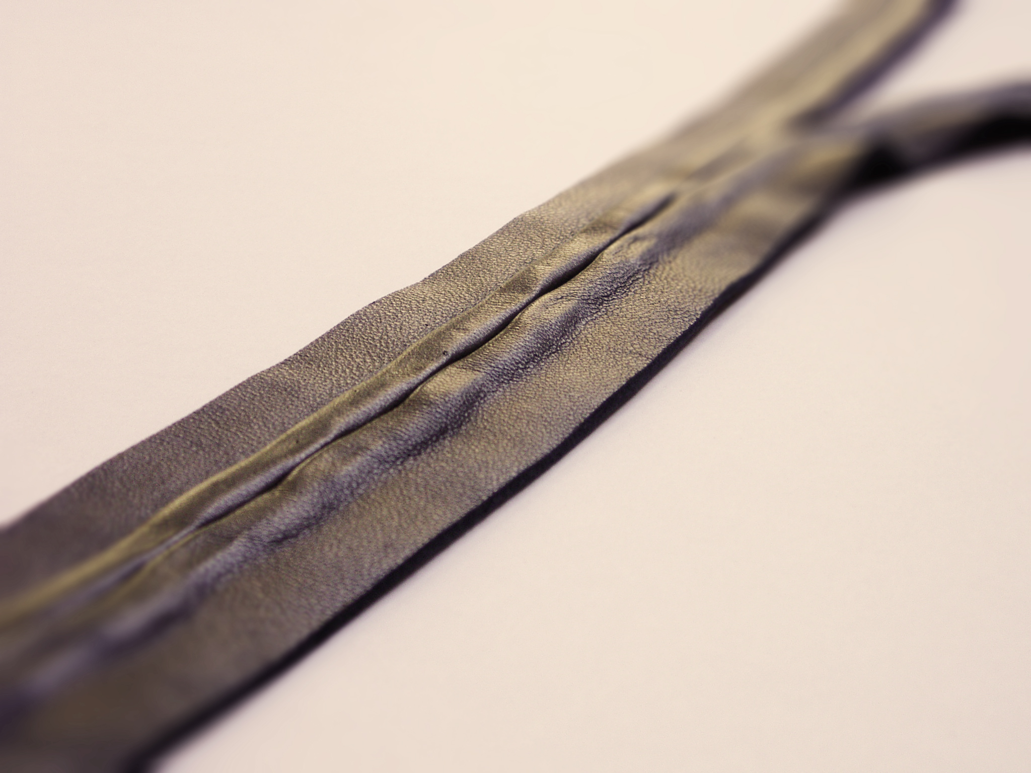
- magnetic closure Real leather

-

- magnetic closure Real leather

19
Accessory by me designed and built as a prototype; It was invented to be able to realize in polyester and in all its variants, as well as with natural materials turned. It is a patent of 1992 ACM. It was developed mainly in two forms:
• the base is always the same, with a small rubber button.
• the counterpart, that is the ring that goes to get stuck is of two types, or a ring in zamak designed with a sporty design, or a simple eyelet large which always goes to to be the counterpart.
The accessory with the eyelet is an accessory that is designed for a classic dress or casual, in fact, with the right combination of materials is easy to imagine an elegant head.
Accessorio da me progettato e costruito come prototipo; è stato inventato per poterlo realizzare in poliestere e in tutte le sue varianti, nonché con dei materiali naturali torniti. È un brevetto del 1992 dell’ACM. È stato sviluppato principalmente su due forme:
-
la base è sempre la stessa, bottone con gommino.
-
la controparte, cioè l’anello che va ad incastrarsi è di due tipi, o un anellino in zama progettato con un design sportivo, oppure un semplice occhiello di grosse dimensioni che va sempre a fare da controparte.
L’accessorio con l’occhiello è un accessorio che è stato ideato per un abbigliamento classico o casual, infatti con la giusta combinazione di materiali è facilmente immaginabile su un capo elegante.


06
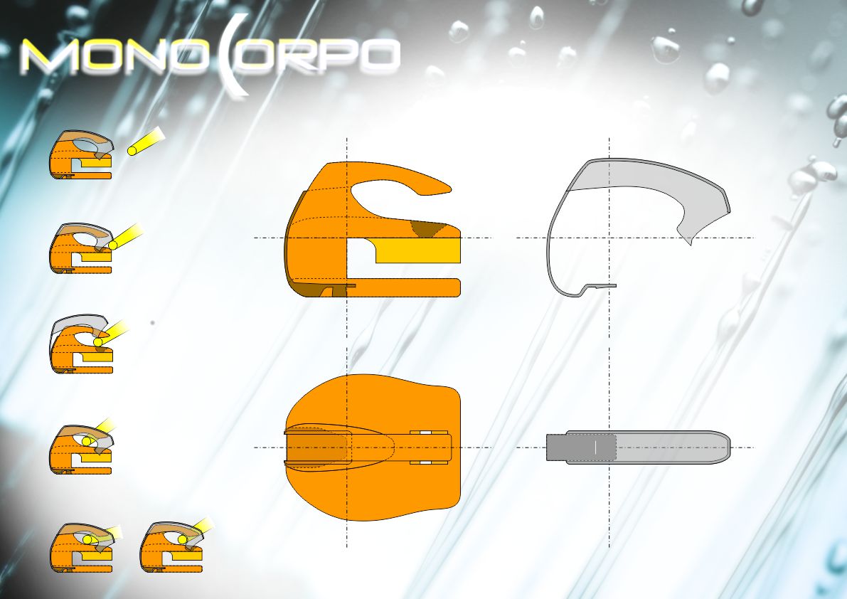
UnicoCoo is an element in its own right, it was later developed a coordinated: “OTTONEcoo“.
UnicoCoo is proof that the blanked is a great way to create innovative products.
UnicoCoo è un elemento a se stante, in seguito è stato sviluppato un coordinato: “OTTONEcoo“.
UnicoCoo è la dimostrazione, che il tranciato è un ottimo sistema per realizzare dei prodotti innovativi.


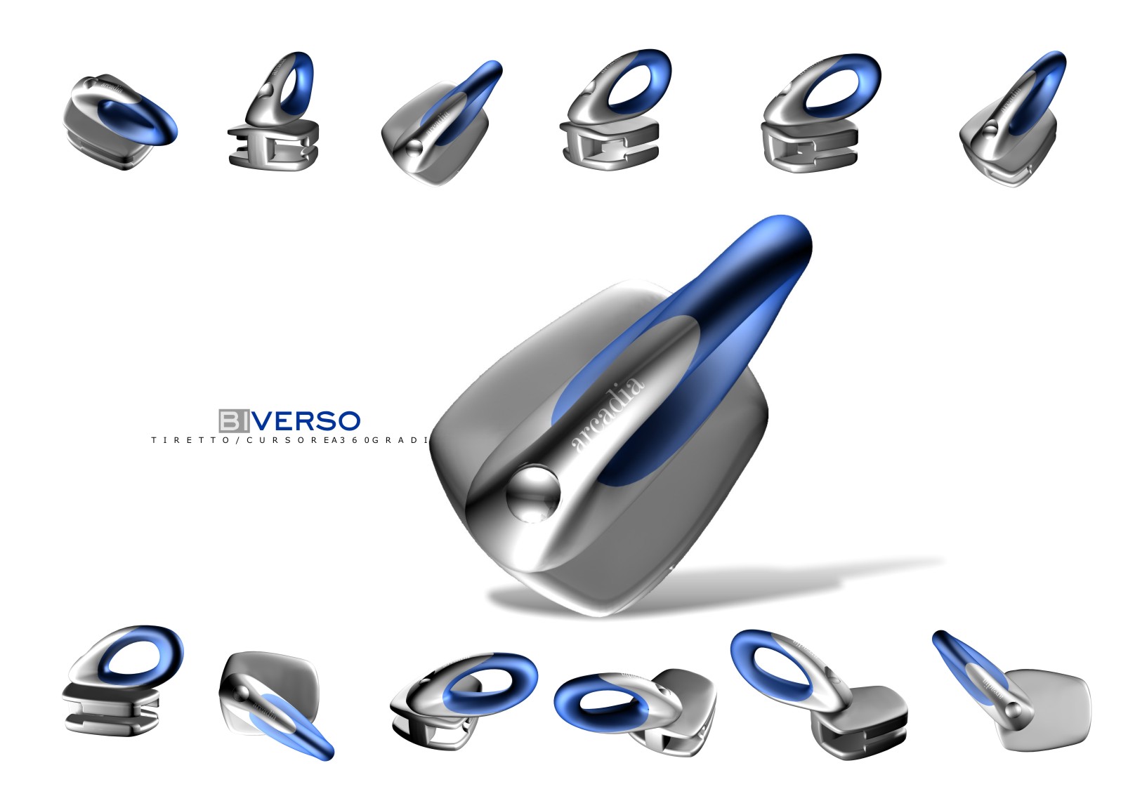
30
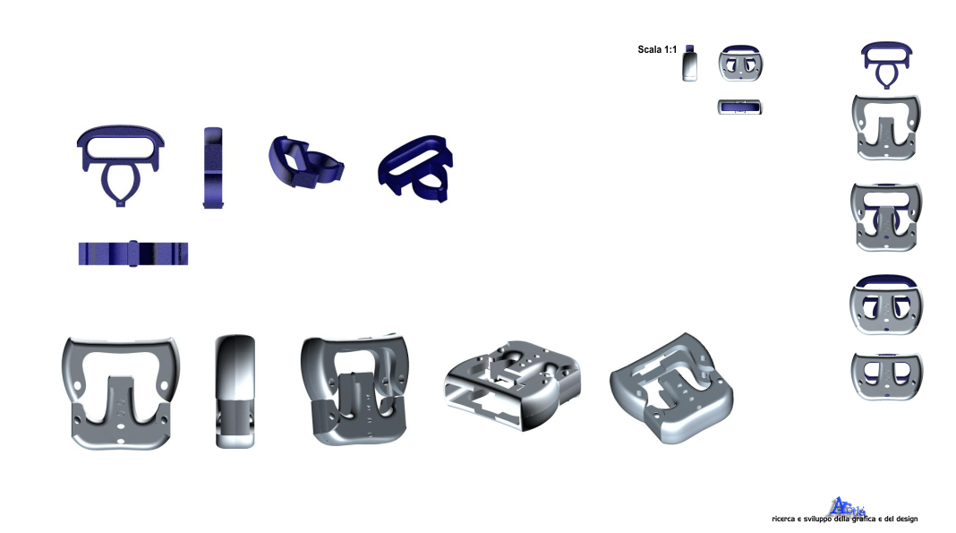
Slider with a carrying handle instead of the puller, enabling better manageability of the slider.
Cursore con una maniglietta al posto del tiretto, consentendo una migliore gestibilità del cursore stesso.


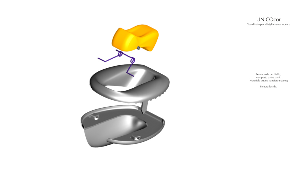
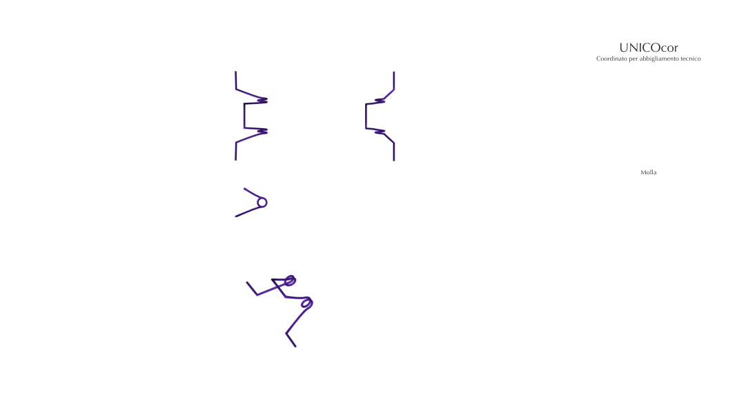
11
Coordinated for technical clothing
Hook in two pieces. Zama and nylon material; glossy finish.
Coordinato per abbigliamento tecnico.
Gancio in due pezzi. Materiale zama e nylon; finitura lucida.
